OmniPoint® is an award-winning wireless multi-point access control solution.
Part 3. OmniPoint Installation Day.
If you have completed the OmniPoint account onboarding process, you are now ready to install your customer’s OmniPoint solution.
Step 1. Your first step on OmniPoint Installation Day is to install the OmniPoint Gateway. It is typically placed in the center of a property, at the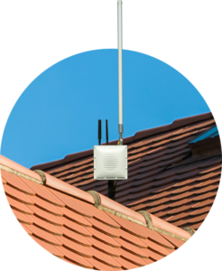 highest possible point. Follow the detailed instructions in the OmniPoint Gateway Install Guide to affix the mounting bracket to the back of the Gateway and to then secure the Gateway to the pole or other object it will be attached to.
Once the Gateway is secured on its mount, you must first attach the necessary antennas.
Keep in mind, OmniPoint Gateways are available in Ethernet or cellular LTE versions – so the installation for each is slightly different; however it is critical that antennas are connected to the Gateway first, and then connect to power.
We will first show you the antenna and power connection steps for an Ethernet Gateway. An Ethernet Gateway will only utilize a LoRa antenna. The cellular LTE ports on the Gateway will not be open.
- First install the Lightning Arrester in the LoRa port.
- Then screw in the LoRa antenna onto the Lightening Arrester.
- The next step is to connect power. For an Ethernet Gateway, plugging in the Ethernet cable into the device will power it up. For this reason, you will not need to use the 12 volt DC plug and transformer provided in the kit – though you will need it for a cellular LTE Gateway installation.
- Then remove the Gateway’s faceplate to expose the Ethernet port.
- Unscrew the black Ethernet port protector at the bottom center of the Gateway. You will see an Ethernet plug there. When purchasing Ethernet cables for the installation, we recommend a CAT 6 cable, though a CAT 5 cable will work.
- Plug the chosen cable into the port inside of the Gateway. You will need to thread one end of the Ethernet cable through the port protector and screw it back on. Connect the other end of the Ethernet cable to the port labeled “PoE ” on the PoE Injector.
- Then using a second CAT 6 or CAT 5 Ethernet cable, connect the port labeled “LAN ” to the main Ethernet router on the property.
- Next, plug in the power for the PoE injector into an outlet. Your Ethernet Gateway should now have Power over Ethernet and a connection to the main router.
- We must now weatherproof the Ethernet cable. We recommend wrapping it with 3 layers of waterproof rubber tape – with 50% overlap. This tape is provided with the Gateway kit and is labeled “COTRAN KC80 ”. Do not use electrical tape. This step does not need to be performed with a cellular Gateway since there would be no Ethernet cable.
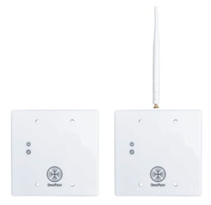
We will now show you the antenna and power connection steps for a cellular LTE Gateway.
- First install the Lightning Arrester in the LoRa port.

- Then screw in the LoRa antenna on top of it.
- Attach the two cellular antennas provided in the LTE-MAIN and LTE-DIV locations. The two cellular antennas in a Gateway kit are identical, and thus they can go in either LTE-labeled port.
- Then connect the power cable to the bottom of the Gateway, and wire the other end to the 12 volt DC transformer/power supply.
All OmniPoint Gateways – whether used outdoors or indoors – must be grounded to protect against power surges. See the OmniPoint Gateway Install Guide for recommendations on how to do so, or contact CellGate Technical Support for input.
Once you have completed all of these steps, power on the Gateway. Check it is functioning properly by looking for the “online” indicator either on the Gateway itself or in the CG Installer Control app. It may take several minutes for the initial online indicator to display.
Once you have confirmed the Gateway is functioning properly, go to the first entry point where an EPM will be installed.
Step 2. You will now wire the first EPM to be installed.
- Start by connecting the main power wire — the 12 volt DC — to the back of your EPM.
- Next, wire your wet relay to your door strike/contact. Please note: a wet relay will send voltage or remove voltage when activated, the dry contact relay will send or remove continuity.
- Then wire your Wiegand device to the correct terminals as shown here.
- The data wires must match on the EPM and your reader.
- The green wire should go to D0 and the white to D1 on both devices.
- Now wire your input to the input 1 terminals. This is a continuity loop that will check for a short to trigger an input.
You have now completed the standard wiring for an EPM installation. Please be certain your EPM wiring looks like this, and only then power up the EPM. Note: there is room for an additional input and a dry contact if needed.
Step 3. Now log in to your CG Installer Control App with the login and password provided to you. Go to the menu on the left side of the app, and choose “Install a Product.” Then select “OmniPoint EPM.” 
Note: if you are installing an OmniPoint solution on more than one property, you will first need to select the correct property prior to choosing “Install a Product.”
Step 4. From the Installation Location screen, look for and choose the Installation entry point that was named during account onboarding. For this example, the first EPM to be installed is for the “Pool Gate,” and thus we select that location.
If EPM locations were not pre-named during account onboarding, the property manager may do so via their TrueCloud portal account or with assistance from CellGate’s Gold Key Service team.
Step 5. The app will then ask you to register the EPM by hitting “Scan Node Barcode,” and it will ask for access to your camera. Please hold the EPM to be installed on its side, and use your phone or tablet’s camera to scan the EPM’s QR code to assign it to that location.
Step 6. Once the EPM’s QR code has been scanned, a message will pop up showing that registration was successful. Now click “Configure & Test.”
Step 7. Verify the green light on the EPM is blinking slowly, at the rate of approximately once a second. If it is, click “Yes.” If it is not, click “No.” Clicking “No” will take you to a troubleshooting step. Otherwise, we can click “Yes” and proceed to the next step.
Please keep in mind it will take about a minute for each EPM to register with the system. You will see the red and green lights blinking until it gets a steady green heartbeat.
Step 8. Once you have selected “Yes”, then choose “Set Trigger Times.”
- 1st set the “Relay” time the property desires in seconds. Relay time is the amount of time a gate/door stays open when activated.
- Then set the “Wiegand” time in seconds. Wiegand time is the amount of time a gate/door stays active when a Wiegand-based transaction is made.
- And lastly, set the “Request to Exit” time in seconds; this is how long a gate/door remains open after a request to exit is made.
- Then tap “Save.”
Step 9. Next, you will “Set Re-Arm Times” by tapping on that option.
- Set the “Re-Arm Wiegand” time in seconds. This is the number of seconds the device will ignore the same code being used.
- Then set the “Input 1” time in seconds. This is how often the input switches states and how often input 1 changes are logged.
- Lastly, set the “Input 2” time in seconds. This is how often the input switches states and how often input 2 changes are logged.
- Then tap “Save.” This is the number of seconds the device will ignore the same code being used.
Step 10. Lastly tap “Push Changes to Device” at the bottom of the screen to save your information.
If you happen to receive a push error message, power cycle your EPM and then wait for the green heartbeat again, then click Proceed.
Step 11. Once the settings have successfully been pushed to the EPM, you can test to ensure it is working correctly.
- First activate the relay by tapping “Send Command”. This should trigger a closed gate/door to open.
- Please confirm the door opened. If the command was successful then tap “Yes;” if it was not, tap “No”.
- Next verify the gate or door’s status by opening and closing the door to ensure the status is correct. If OmniPoint is working correctly, the gate/door status displays as either Opened or Closed based on its current state. A gate/door status of “Unknown” indicates the system is not receiving data from the door status sensor. If you choose not to use gate/door status for any reason, click Skip.
- Then tap “Yes” to move to Wiegand testing.
Step 12. Now it’s time to verify that the OmniPoint EPM is reading Wiegand codes correctly.
- Tap “Start Test.”
- To test, scan an RFID card or enter a Wiegand code at the entrance. Verify that the Wiegand information you entered displays in “incoming data” in the app. An incorrect or blank code generally indicates a wiring problem – the most common wiring problem is the D0 and D1 wires being reversed.
- If all looks good, tap “Yes” to move on to testing Exit Requests.
Step 13. The app will prompt you to send a Request to Exit to verify the process is working correctly.
- You will see a popup that asks if you have a request to exit. Tap “Yes”.
- Now verify the door’s status by opening and closing the door to ensure the status you see is correct. Tap “Yes” if the command worked. The Door Status should display Open or Closed, and match the door’s actual state. If the Door Status is Unknown, the request to exit did not work and the system is not receiving data from the EPM.
Step 14. Once all of the EPM’s functionality has been tested, a message displays stating, “Great! Installation setup completed.”
You may now choose to either “Install another device on the property” or hit “Done” if you are finished. Choosing “done” will return you to the main app dashboard.
Step 15. Once you have installed all of the EPMs at the location, you can review the setup or retest any or all EPMs.
- Choose the property location.
- Then select the EPM gate/door location you wish to review or test.
- You are now on the main function screen for the chosen EPM. From here you can do various tests, and also go back and change the settings that were configured previously if needed.
If you have any questions on the Installation process, please contact CellGate Technical Support at 855-694-2837, then hit Option 2.
Thank you for choosing an OmniPoint solution!